 Assembling the Hamptone HJFP2 Microphone Preamp Kit
Description | Assembly | More Photos | Conclusions | ^ Studio Page
Description
On my quest for a high-quality but not silly-priced microphone preamplifier, I came across the Hamptone website, featuring a distinguished set of preamp kits as well as ready-made models, in both solid state and valve designs. Reviews of this gear in audio/DIY forums have been very positive all along, so I decided to try out the HJFP2 and ordered a kit.
NOTE: If you want to skip the technical yaddayadda, you can jump straight to the results & conclusions!
The Hamptone JFET Preamp is a 2 channel discrete, transformer balanced, 'Class A' J-FET design, which may need some explanation:
- Discrete means that the parts inside the unit are not based on integrated circuits, such as op-amps, ICs or similar parts. All electrical parts are separate resistors, capacitors, transistors, and the like. There are various different opinions about whether this is absolutely desirable and necessary, and I would not draw any conclusions from the fact that a given design is based on discrete components or not.
- Transformer Balanced means that both the input and the output stage are guarded by large, generously oversized custom transformers that can add some gain and also do some nice things to the audio. If fine-tuned appropriately with the proper knowledge of resonances and buffering, this design comes close to the legendary preamp designs done in the 70s and 80s by Rupert Neve, with a sound that many people describe as sweet, slightly coloured, and musically pleasant. Of course the entire design is based on balanced inputs and outputs.
- Class A in short means that the audio waves are put on top of a DC offset, so that the current never crosses the 0 V line, thus providing less distortion and clearer reproduction. The decreased efficiency when it comes to power consumption can be neglected in a preamp design.
- JFET stands for Junction Field Effect Transistor. In a nutshell, these behave a little bit less than normal transistors, and a little bit more like valves/tubes in their way of treating the electrical current, visible in the characteristic curves for the corresponding parts at a certain voltage. This leads to a softer sound, compared to a simple transistor design, when the design is approaching its clipping level. Some describe the typical JFET sound as "liquid" or "silvery," whatever exactly this may imply for the physical behaviour of the circuit.
The Assembly
Soldering and physically assembling the unit took a weekend, and another two days were used for testing the device, cleaning up all the PCBs, and finalising the whole thing. This roughly equals 30 work hours, spread over about a week, and I would strongly advise against doing this in any form of rush. Take your time. Let me stress that the included documentation is very good, and there should be no need to contact the designer with your queries unless you have a real showstopper.
As Scott Hampton mentions on his website, this is not a kit for beginners, even though some beginners managed to build it successfully. You should be experienced in soldering, handling electrical circuits, have an antistatic work environment, and, for the love of God, be constantly aware of the lethal effects of high voltages.
The box with the kit took about 2 weeks to ship from Portland/OR to Cork/Ireland. It contains this...
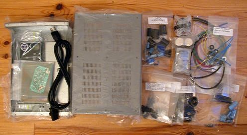
...which is a well-prepared, ≈250 part assortment down to the last screw and the last cable binder. The documentation is well written and explains every step in good detail. As with any good documentation, most issues during the building and testing process can be solved by just reading it. However, the technical support that Scott Hampton delivers is brilliant with very short response times. I experienced this myself when I had some perceptual problems with my final test setup, and the replies were prompt, detailed, and very friendly.
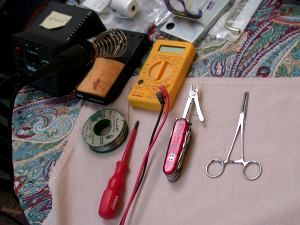
My toolset consisted of the following items:
- Weller soldering iron (regulated, with temperature dial)
- 1 mm Radio solder with embedded flux
- Victorinox Cybertool™
- Artery clamp
- Digital volt meter
- Phase indication screwdriver (essential!)
- Selection of screwdrivers
- Electric insulation PVC tape
- Heat shrink tube
You should also have some tissues ready for wiping solder and flux. For the final cleanup, get some Isopropanol (IPA, ≥ 70%) and Q-tips.
More Photos
|
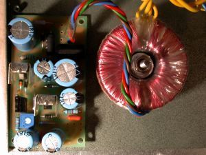
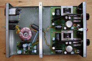
Power Supply Unit with toroid transformer. The transformer can be rotated to minimise electromagnetic interference |
|
The bomb proof casing has all the holes, threads and raisers already built-in |
|
|
||
|
A regulated soldering iron is your friend. You can adapt the temperature for every part you deal with. |
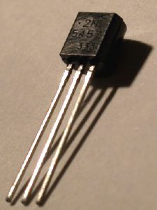
One of the JFETs, which come pre-biased, i. e. calibrated for best performance by matching them with a corresponding resistor |
|
|
|
||
|
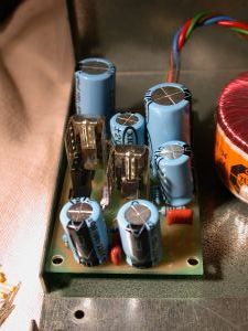
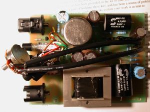
Audio channel board. Note the round, shielded input transformer (top), the large output transformer (bottom), and the deliberately overengineered capacitors. The actual transistors and JFETs are slightly dwarfed by the other components. |
Final assembly. I added a ferrite core, which is not strictly necessary, and some insulation PVC tape for additional high voltage safety. I also used heat shrink tube for the high voltage cables. |
|
|
|
|
|
|
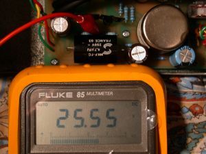
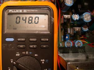
Testing the main DC power; make sure you use a good volt meter |
Adjusting the phantom power |
|
|
|
||
|
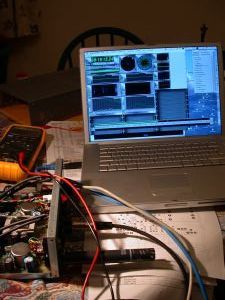
Testing the audio channels using a the PowerBook as calibrated signal generator and analyser simultaneously (AudioTest and SpectraFoo™). This is for testing that the gain stages work as expected, and that both channels behave the same. |
Visualising the noise floor, see below. Note that the condensor microphone is plugged in, but the phantom power is off. This is for terminating the balanced input for neutral measurement. |
|
|
|
||
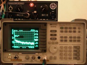 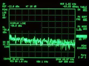
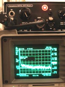
Visualising frequency range and noise floor with a Hewlett-Packard spectrum analyser. Note that the figure is taken at full blast without a load, which is not representative and was only done for comparison. Also, the scale of the display is deliberately exaggerated, like on mountain charts. The higher left side is due to the filter setting, not the noise. The objective, real-world noise figures are very low. Making these measurements is not necessary to get the HJFP2 to work, you only need to do this if you are a as spoiled and picky as I am, and have a spectrum analyser in your neighbourhood. |
||
Results & Conclusions: The HJFP2 in Real Life
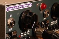
Features. The HJFP2 does largely without bells & whistles, but you will appreciate its rugged case design and the straightforward interface. The functions are well thought through and you can see that no out-of-control marketing department was present to touch up the feature set—no clipping light, no fancy blue LEDs, no retro VU meter, no filters. However, working with the unit shows that you don't really need any of those anyway, and personally I have plenty of other LED chains to worry about. Here, the designer put the resources where they made a difference to the sound.
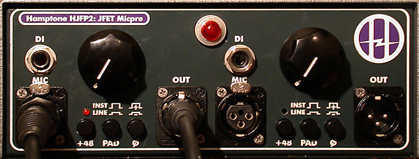
You can be absolutely sure that the preamp has all the features that are essential for real work, such as balanced XLR microphone inputs and outputs, line level and high-Z (2.2 MΩ) DI inputs, slow ramping 48 V DC phantom power, -14 dB pad, and phase invert buttons for each channel. See picture below.
Comparison. The HJFP2 features a generous and healthy 76 dB of gain, which is plenty for any conceivable recording situation. In fact I cannot remember ever using the maximum gain setting in practice. I took some time to compare it to a friend's Focusrite ISA 428, which has a similar design philosophy while costing three times as much for 4 channels, aside from running very hot and coming apart after one year, with knobs falling off and some of the features not working any more.
I found that the gain levels of the two are only minutely different and the sound is just a little sweeter on the Hamptone preamp, as far as my ears can tell and time allowed. Noise on both models is negligible. I also found that with the Focusrite's separate controls for impedance, range, gain, and low-cut filters, you can spend more than just a few moments "optimising" the settings, while on the HJFP2, it's just one knob, end of story, and anything that comes out of it sounds rather lovely.
Conclusion. I don't have the usual "verdict," since this not a product review and I'm not getting paid for writing this. But the HJFP2 has been a joy to use so far, and it seems hard to make anything sound bad with it. In fact I just ordered a second kit for the tube version...
For the moment I conclude that the HJFP2 is quite a serious piece of equipment that plays in the same league as the Focusrites, Avalons and Crane Songs of this world, at a fraction of the costs.
Finally, if you don't have the time or the patience to put it together as a kit, there is also the option of ordering a fully assembled and tested unit from Hamptone. The pricing for either the kits or the ready-made units is so low as to suggest a hint of self-denial on the side of the designer. Or maybe he's simply a very nice guy.
The HJFP2: Brilliant technology, reasonable price, fun to build
Go to the Hamptone website